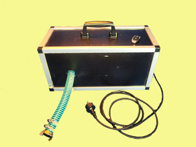
Bee feed syrup pump 1.0
The bee feed syrup pump allows you to pump highly viscous feed syrup from one feed tank to another or directly into the feeding trough. This makes the physically demanding task of feeding the bees much easier.

Materialliste
Mechanical structure:
The impeller pump is connected to the stepper motor via the coupling. The stepper motor is bolted to the base plate using a stepper motor mount. The pump is raised over a piece of the screen-printed plate and can then be attached directly to the base plate. The two hose fittings with the ¾-inch internal thread are mounted on the pump. Then, two pieces of hose, approximately 30 cm long, are connected to the hose connection using two hose quick connectors each. The quick connectors are then attached to the other two ends. These can only be installed once the hoses have been pulled through the housing walls.
Electrical connections:
1.) Supply voltage stepper motor driver
The DM2282 stepper motor driver can be operated with a mains voltage of AC 230V. However, to enable the pump to be turned on and off via a radio remote control, a radio switch is also required. The power cable is connected to AC Input L (brown) and N (blue).
The output of the wireless switch AC Output L and N are then connected to the terminals of the same name on the stepper motor driver.
2.) Connect the stepper motor to the driver
Next, the two coils of the stepper motor (coil A: A+ and A-, and coil B: B+ and B-) are connected to the stepper motor driver. It's important to note that the colors of the connectors are not standardized and vary from stepper motor to stepper motor. You can find the correct assignment in the datasheet or determine it by measuring.
How do I determine which wire belongs where?
Method: Measure resistance (multimeter)
Measure the resistance between all wire pairs.
Two pairs each show low resistance (~1–100 ohms): these are the two coils.
Assign these four wires accordingly:
Coil 1: e.g., A+ and A−
Coil 2: e.g., B+ and B−
The polarity (plus/minus) is not critical for function – but important for the direction of rotation. You can simply experiment: If the motor runs backward, swap A+ with A− or B+ with B−.
3.) Connect the PWM module (speed controller) to the stepper motor driver
The speed of the stepper motor can be controlled via a PWM module. For this, we use the PUL signal. To change the direction of rotation, we also use the DIR signal. The PUL and DIR signals of the stepper motor driver are then connected to the GND of the PWM module.
The PWM module then requires a supply voltage between DC 5V and 30V. For this, we use a 24V 18W power supply. The power supply receives its supply voltage directly from the power cable L (brown) and N (blue). The outputs RD+ and BK- are connected to the PWM module's DC+ and DC-.
Commissioning:
Once the feed syrup pump has been completely wired, all connection covers must be closed and the housing assembled. The device can now be plugged in. The feed syrup pump can now be switched on using the remote control. The pump starts working as soon as the CW or CCW button is pressed. These two buttons can be used to determine the direction of rotation of the pump. Make sure that the speed is not set too high when starting the pump, as this can cause the pump to lock. If this happens, the pump must be restarted (disconnect from the power supply and restart). The speed can be set separately for both directions of rotation using the rotary knob.

